How to Select Planar Magnetics for Low-Profile, High-Reliability Smart Grid Designs.
How to Select Planar Magnetics for Low-Profile, High-Reliability Smart Grid Designs
Introduction
Electrification has become the new buzzword in 2020s thanks to the renewed focus on developing and integrating renewable
energy technologies. Renewable energy generation and broader electrification require a completely new approach to structuring
the electric grid, locating power systems, and determining operational requirements for key pieces of power generation and
distribution equipment. If climate concerns are to be addressed and in order to diversify the world’s energy portfolio, electric
grids need to be smarter so that they can integrate generation and distribution capacity from multiple sources.
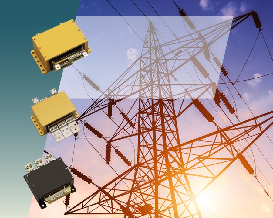
Renewable energy power systems and smart grid technologies must also operate under the same basic sets of principles and perform similar tasks at multiple points throughout the grid. Even as the renewed focus on smart grid technologies drives new system architectures, some fundamental components will always be needed in power conversion and regulation systems. In renewable energy systems, whether at the utility level or at smaller scales in people’s homes, safety and reliability are critical. Power systems for smart grid technologies and to support the next wave of renewables need to have high uptime and consistent performance.
Reliability challenges in smart grid power systems that integrate renewables with traditional fuels can be found in areas like power conversion efficiency, heat management, and current handling capabilities. Obviously, these systems need to be reliable when operating at high power and while generating a lot of heat, but they also need to integrate with a grid without injecting “dirty” power back into the grid. Smart grid power systems must also operate as embedded devices that pack plenty of digital functionality into the same package as typical power handling circuitry, creating pressures to save space as devices are miniaturized and power densities increase.
Planar magnetics are one alternative class of magnetic components for use in smart grid power systems. Planar transformers and inductors carry several advantages over a typical board-mounted transformer or inductor coils, which are facilitated by their lower profile and unique structure. The compact structure and design of these components can help power systems designers balance their form factor, size, weight, and current handling goals. Planar magnetics have similar current handling capabilities as larger magnetic components, but they are superior in terms of power conversion efficiency and thermal management, making them a natural choice for use in high-reliability smart grid applications.
Planar Magnetics Requirements in Smart Grid Systems
Magnetics for power systems are normally selected by first looking at the current and voltage handling needs in order to reach
a target power output during conversion and regulation. This means the inductance value, voltage/current rating, and parasitics come into focus when selecting planar magnetics, as footprint and height optimization is a given. This is the typical approach when selecting off-the-shelf components, which are limited to specific form factors for chassis-mount or board-mount magnetics. Planar magnetics enable a new approach to transformer and inductor selection by allowing the form factor to be an important consideration that drives component selection.
Why should designers focus on form factor as part of smart grid systems design? The envisioned smart grid won’t be enabled by large distribution systems or utility substations, it will be enabled by systems that intelligently capture and distribute power at the micro level. In terms of design and layout, these systems need to integrate high power handling capability alongside a digital control section so that the end device can make intelligent power routing and delivery decisions. Keeping all of these functions in a single package with sleek form factor requires addressing the bulkiest components in these designs, which tends to be the magnetics. Planar magnetics have a major advantage in this area compared to off-the-shelf transformers with comparable electrical specifications.
Advantages of Planar Magnetics
While small form factor is certainly an advantage in terms of physical layout and enclosure design, the relative power density of planar magnetics produces important electrical advantages that are highly desired in smart grid systems.
Size and weight
Planar magnetics can be used in lower profile systems as they have a smaller dimension in the z-axis. The tradeoff is that these designs are spread out over a larger board area. However, the smaller vertical size, winding orientation, and magnetic core orientation provide strong coupling between the magnetic field and the core material, thus less of the high-density magnetic material can be used to hit a given inductance target. This ability to use less material to hit a given inductance target means planar magnetics can have lower weight compared to off-the-shelf magnetics with comparable electrical specifications.
Current handling
Smart grid systems must be able to deliver high current in order to support tasks like battery management and distribution. Planar transformers tend to have high current ratings and can operate reliably in high power delivery scenarios. The current handling ability of these components is ensured through their lower DC resistance due to the use of less winding material, thus they do not experience as much power loss as off-the-shelf transformers through Joule heating.
Low flux loss
Smart Board-mounted transformers may have a shell or laminated core structure, and they will not perfectly confine the magnetic field in the core material. Inductors may have loose windings about their core that also allows for flux leakage due to imperfect coupling. Planar magnetics adopt a structure similar to what is used in a shell-type transformer to ensure strong coupling to the core material by generating larger magnetic flux over a much shorter distance. The result of this stronger coupling between the magnetic field and magnetic core is lower leakage inductance and higher power conversion efficiency (in planar transformers) than a laminated core structure or wire-wound structure.
Easier thermal management
Cooling is important for ensuring a power system can operate reliably, including as part of energy management within a smart grid. Planar transformers can be easier to cool via conduction due to the structure of the component packaging. The large flat surface on a planar transformer is a good location to attach a heat sink, or the heat sink can be integrated into the packaging. Attaching directly to an enclosure is also an option. However, the tight structure of these components can make them difficult to cool via forced airflow, but the span of these components and ease of heat sinking can compensate for difficulties in convection cooling.
Important Specifications for Planar Magnetics in Smart Grid Systems
Input / output power handling
This is typically the starting point for selecting magnetic components, specifically transformers. Inductors also have voltage and current limits that determine their power handling capability. In addition to the rated input/output voltage and current, there is a power conversion efficiency specification to be considered. The shell-type design in a planar transformer provides strong inductive coupling that ensures high power conversion efficiency across the device. The power conversion specification shown in a datasheet normally corresponds to the input/output power handling specification within the operating frequency range and at full power output (after rectification).
Primary-Secondary isolation
For planar transformers, the prisec isolation between coils is a measure of their breakdown resistance and is normally specified as a DC voltage difference. Isolation voltage values can reach kV levels in planar transformers. In power systems, isolation is important for safety as this will determine the minimum level of galvanic isolation the component can provide. This specification should be compared with safety regulations or industry standards to ensure a design can meet safety targets.
Switching frequency limit
Parasitics in the structure of a planar magnetic component will limit the useful switching frequency (see more on parasitics below). Above this limit, the component becomes capacitive and could begin coupling high dV/dt pulses around the system, which would interfere with nearby digital components. Although planar magnetics tend to have lower frequency limit, this makes them useful in standard topologies like H-bridge converters or resonant converters, including the bidirectional converters used in EV charging stations. Other smart grid power systems use similar low frequency topologies and bidirectionality, making planar magnetics ideal candidates for these systems.
Cooling method
Planar magnetics components can be difficult to cool via forced airflow simply because they are so compact. Heat must be dissipated through the package into a heat sink, which can then be used as a channel for forced airflow. The transformer package should be selected such that the mounting or bonding method will enable the required cooling method. This may mean mounting to the enclosure so that heat can be dumped directly into the system chassis. The mounting style and package aspect ratio will both determine which cooling methods will be more feasible and effective in planar magnetics.
Mounting style
Planar magnetics components can be placed on a PCB as SMD components or as through-hole components. Alternatively, for physically larger components, they could be mechanically mounted to a PCB or directly to an enclosure. In terms of innovative power systems, the mounting style could allow an enclosure to be incorporated as part of a thermal management strategy by creating a path to conduct heat directly into the enclosure or chassis. This can help compensate for the cooling challenges in a planar magnetic component running at high current, something which would be regularly expected in a power delivery system.
Parasitics
The principle factors that create power losses and noise coupling in power systems are parasitic R, L, and C, all of which should be minimized when selecting inductive components. Because planar magnetics are very tightly coupled to their core ferrite material, they tend to have lower parasitic leakage inductance, which will in part determine the power efficiency of planar magnetics. The total DC resistance of the coil winding will also contribute to the current limit and power conversion efficiency in planar magnetics, with other factors being cooling method packaging style. The lumped capacitance of planar magnetics tends to be high compared to off-the-shelf transformers, which could create challenges with common-mode noise circulation. Designers should consider the need to minimize the lumped parasitic capacitance when selecting planar transformers.
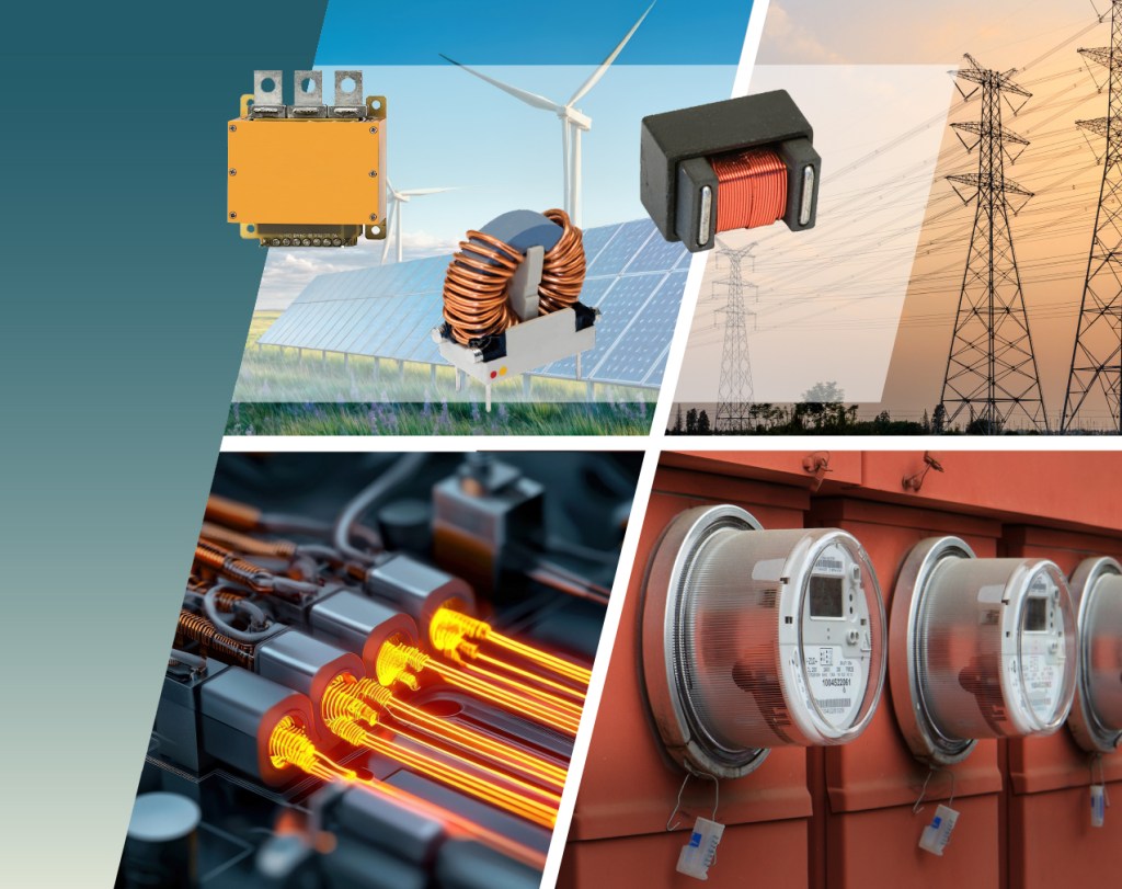
Choosing Planar Magnetics for Various Application Areas
A diverse array of equipment is used in power systems to support smart grid technologies, ranging from small charging stations to monitoring equipment, energy storage systems, and large distribution equipment. The important specifications on planar magnetic components depend on the application area and deployment environment.
For power conversion and regulation systems, efficiency is a primary focus alongside input/output power handling requirements. Most systems deployed at the local level will need to be designed with these requirements in mind within a standard converter/regulator topology. As systems scale up in terms of power handling and input/output voltage, safety becomes an important factor, and isolation becomes a more important consideration. All of these systems must be reliable and have perpetual uptime, which is where mounting style and thermal management become important considerations, particularly for equipment with high power handling requirements

Summary on Smart Grid Planar Magnetics
Advanced power systems for power distribution and regulation need to be highly reliable and efficient. Planar magnetics are ideal components that help satisfy objectives in both areas. These components allow power electronics designers to balance form factor with power handling capabilities while also ensuring high efficiency as would be demanded in smart grid power systems. The modular nature of planar magnetics components also enables custom designs that can accommodate standard input and output voltages used in the existing electric grid, EV power systems, industrial power systems, and many other areas.
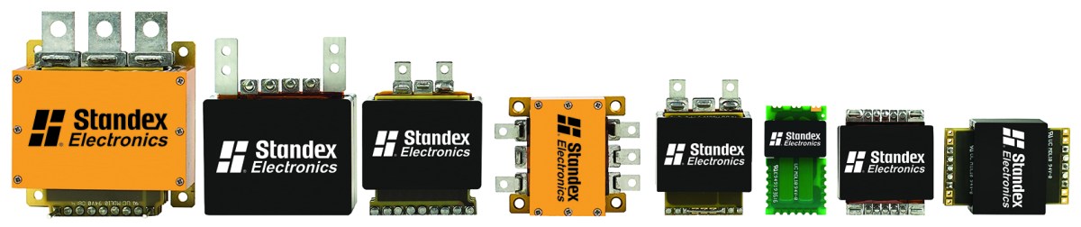
Designers who are considering using planar magnetics in their smart grid power system designs should consider the broad line of planar magnetics products from Standex Edge. The planar transformer and inductor options from Standex Edge are designed to provide high efficiency power conversion and regulation with high power and current limits in power system designs. Contact Standex Edge today to learn more about its line of high power, high reliability planar magnetics components.
Related Articles
-

Running Smoothly
How Standex Edge Took Incomplete Product Specifications to a 1,050% Production Increase in 10 Months.
-

How Standex Edge Supports Industrial Systems
How Standex Edge Supports Industrial Systems with High-Reliability Magnetics.
-
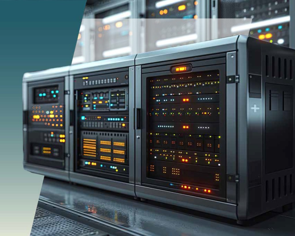
Reducing Data Center Energy Waste
How custom magnetic design is maximizing Data Center power efficiency and why the move to 48 V and 800 V architectures makes magnetic optimization mission-critical for AI-era infrastructure.
-
The Edge of Electronics
How the new brand of Standex Electronics defines the established expertise and global impact of its Power Magnetics division.